Frequently Asked Questions
Why are HLPW-4 and HLPW-5 being conducted differently than previous high-lift workshops?
Bottom line: to try to get more out of the workshops. In an attempt to accelerate the rate of progress, and to take better advantage of the collective brain-power focused on enhancing CFD prediction capability for practical high-lift aerodynamics, the committee decided to try something new for HLPW-4. Rather than working individually, active participants were asked to join one or more Technology Focus Groups during the months leading up to the workshop. The new way of operating HLPW-4 worked extremely well, so we are continuing the practice with HLPW-5. As a side note, starting with HLPW-4 we changed the workshop acronym from HiLiftPW to HLPW. However, the workshop’s website name still uses “hiliftpw”.
What are Technology Focus Groups, and how do they work?
A Technology Focus Group (TFG) is made up of ACTIVE PARTICIPANTS working (remotely) together in a specific area, to try to answer questions related to CFD prediction of high-lift flows. Each member of a TFG contributes to team activities, as delineated by the TFG leaders. These activities likely involve performing CFD or meshing work, and sharing it with the TFG team. (It is possible that each TFG may be conducted somewhat differently.) At the HLPW-5 workshop itself, each TFG will present a summary of its results. In summary:
- The work is now part of a broader team’s collective efforts.
- Rather than reporting results individually at the workshop, active participants are interacting regularly with their TFG, and sharing their results with the TFG in the months prior to the workshop. Individual active participants are no longer responsible for making a presentation at the workshop.
- Instead, the TFGs are responsible for summarizing their collective results and presenting them at the workshop.
How can I attend the workshop if I am not presenting my own work in an individual presentation?
It is hoped that organizations will still encourage their employees to attend the workshop in order to see all of the TFG summaries, and to actively participate in the workshop discussions.
Do I have to join a TFG to attend HLPW-5?
No. If you are not a member of a TFG, then your status is OBSERVER. Observers are free to run the test cases, use the grids, etc. But their results will not be included in the collective summaries presented at the workshop. Observers can also do nothing - just observe, because they are interested. Like everyone else, observers can attend the TFG meetings and/or the HLPW-5 workshop and join in the discussions there. In other words: Anyone, including active participants and observers, may attend HLPW-5 (subject to possible space availability/restrictions).
What do I need to do to attend the workshop?
To attend the workshop, both active participants and observers must register for HLPW-5 with AIAA. AIAA will also give details regarding travel and accomodations, visas, etc. Note that registering for the AIAA Aviation conference alone does not give you access to HLPW-5 (and vice versa). You must specifically register for HLPW-5, and pay its additional registration fee.
What happened at the first four high-lift prediction workshops?
Lots! The websites containing much of the data and conclusions are still available following the dropdowns above. Additionally, please see the publications page for summaries from the workshop committee and focus groups.
- HLPW 1: June 2010
- HLPW 2: June 2013
- HLPW 3: June 2017
- HLPW 4: January 2022
- HLPW 5: July 2024
What should I do if I find “problem areas” in the geometry files?
If you encounter any problems/issues as you build grids using the geometry files, please make your own fixes, DOCUMENT everything done, and plan to share your fixes with your TFG. Note that the geometry includes regions that may be very difficult to grid (and possibly solve), including very thin gaps at the bottom/inside edge of the slats. These were present in the wind tunnel configuration, so they were left in. It is up to you how to handle such areas; this is part of the challenge of the workshop. Again, be sure to document every assumption/change/fix that you make, as your grids are created.
It is confusing that the test cases use full-scale geometry yet wind-tunnel-scale Reynolds number (Re). How do I reconcile this, and how do I set Re if my code does not have Re as an input?
It is particularly important that you set conditions to match the prescribed Reynolds number (Re) and Mach number of the test cases. These two parameters uniquely define the flow conditions. If your CFD code does not take Re as an input, then (preferably) kinematic viscosity should be adjusted in order to achieve the precise Re requested in the Test Cases Document. The Re in the three HLPW-5 test cases vary (they are all based on mean aerodynamic chord (MAC)). The MAC is 275.8 inches (full scale). As a specific example, say that you want to run ReMAC=5,600,000 on a grid created in full-scale inches. In this case, the Re per inch should come out to ReMAC/275.8 = 20,304.5685.
Where can I find gridding guidelines for making my own meshes?
We have decided to forgo specific recommendations for meshing in HLPW-5. The reason for this is that the workshop includes many different methodologies, each of which has very different meshing requirements. Therefore, each TFG is taking the responsibility for determining its own “best practices” for creating meshes and families of meshes. For those participants performing fixed-grid RANS, the meshing guidelines from past workshops can provide some guidance if needed. HLPW-3 Gridding Recommendations HLPW-4 Gridding Recommendations
Please describe how to obtain lift coefficient (CL), drag coefficient (CD), and pitching moment coefficient (CMy).
Lift coefficient is defined as L/(qS), where L is the sum of the components of the pressure forces and viscous forces on all parts of the vehicle in the UP direction, taking into account the angle-of-attack. S is the reference area of the semi-span model (Sref/2). The q=dynamic pressure=0.5rho_infU_inf2. Similarly, drag coefficient is defined as D/(qS), where D is the sum of the components of the pressure forces and viscous forces on all parts of the vehicle in the DOWNSTREAM direction, taking into account the angle-of-attack. Moment coefficient is defined as M/(qSc). Here, M is the moment about the moment reference center (MRC), and c is the mean aerodynamic chord (MAC). This workshop is asking for pitching moment coefficient, which is taken about the y-axis pointing out of the MRC. To get M, you need to sum up all of the local forces (pressure forces and viscous forces) times their moment arm about the MRC’s y-axis. By convention, CMy is positive when it acts to pitch the aircraft nose UP. When computing the model in the wind tunnel, the model’s standoff should not contribute to the computation of CL, CD, or CMy. The MAC, reference area (Sref/2), and MRC location are provided on the Geometry Files page. Note that the MRC is with respect to the particular coordinate system in which the geometry is provided (full-scale, in inches, with origin in front of and below the model nose). Y=0 is on the model’s centerplane. 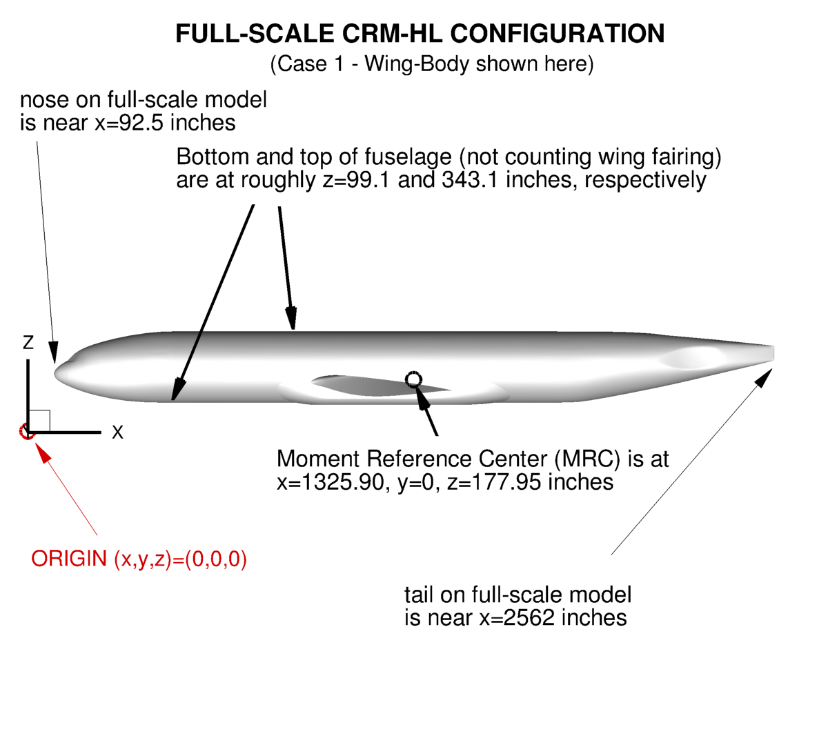
What is a PID and how do I use it?
A PID is a Participant IDentification designation. It is the way we identify the submitted data for the workshop. PIDs will be assigned to each participant and/or team.
I tried to use the provided grids, but my solver would not work with them. Can I make modifications to these grids?
Yes. Be sure to DOCUMENT everything done, and plan to share your changes and experiences with your TFG.
In what formats are the grids provided?
A variety of different formats are used, depending on the person who created the grid and the needs of the intended TFG that will primarily make use them. Typical formats in the past have been CGNS (.cgns) and AFLR3 (.ugrid). Most organizations have the ability to read at least one of these formats. CGNS files are self-contained, whereas AFLR3 files include separate mapbc files.
Can/should I submit an AIAA paper on my HLPW-5 related work for a future AIAA meeting?
Participants are free to publish/show their own results any way and at any time that they want. However, regarding AIAA papers, the HLPW committee prefers that participants wait until they hear about the opportunity to participate in HLPW special sessions, likely to be held at one of the conferences after the workshop (after 08/2024). The reason for this is so that related papers are grouped together, resulting in more cohesive workshop documentation.
Do the geometry or grids include angle of attack?
For free-air, no. The geometry and all free-air grids are provided with the CRM-HL aligned with the x-direction, corresponding to angle of attack of zero degrees. Furthermore, extraction of CFD data is all specified with respect to the unrotated full-scale model. To run in free air at an angle of attack, the freestream flow needs to be rotated, as per typical CFD procedure. If used, in-tunnel geometries are to be assembled yourself. Any provided in-tunnel grids should have the model rotated appropriately with respect to the tunnel walls.
Are there rules for using data from this website?
All data (including images) provided on this website are publicly available and can be used freely, subject to rules and limitations established for NASA websites (which generally states that any information must be used in a factual manner, not manipulated or altered, and not used in any way that implies endorsement). Appropriate credit should always be given when showing or publishing material produced by other authors. This includes use of the experimental data provided on this website by the workshop committee. For example, use of ONERA or NASA experimental data should be credited to those organizations.